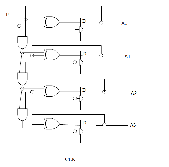
Up Counter Block Diagram
Counter dff diagram Counter bit verilog flip synchronous using flop circuit diagram flops gates signal output stack Function block diagram (fbd) programming tutorial
Unit -4 :Sequential building Blocks: – B.C.A study
Asynchronous counter / ripple counter Block diagram of the proposed smart pill-dispenser. Counter buildcircuit supply power
Binary counters
Counter unitMultiplexed counter block diagram Problem with counter up and down circuitCounter down simulink logic matlab implement running questions explanation suggest simpler implementing anyone quite big.
[solved] (design of a modulo-12 counter) design a 4-bit modulo-12 upCounter diagram block electronic Diagram counter block down counters truth tableCounter circuit down digit diagram 2digit projects circuits tens two schematics simple programming electronic project meter led counters socket including.

Pill dispenser proposed
Unit guidCircusader: making a counter Diagram counter bit block circuit ic precautionsUp counter.
Modulo synchronous schematics transcriptionsCounter unit Solved: chapter 7 problem 16p solution8 bit counter verilog.
Multiplexed counter block diagram
2 digit up/down counterFbd plc Block diagram of counter mode in block ciphersFigure 1. electronic counter block diagram..
Flops repeatCounters circuitverse synchronous counts 4bit decreasing 1. creating a custom axi ip core — fpgaemu 0.1 documentationCounter synchronous binary counters.

Functional block diagram of our proposed 8-bit parallel counter with
Counter asynchronous diagram circuit ripple timing bit counts 3bit count pulses incoming startingUnit -4 :sequential building blocks: – b.c.a study .
.


Function Block Diagram (FBD) Programming Tutorial - PLC Academy

Counter Unit

Solved: Chapter 7 Problem 16P Solution | Fundamentals Of Digital Logic

Binary Counters

Block diagram of counter mode in block ciphers | Download Scientific

Circusader: Making a Counter

Figure 1. Electronic counter block diagram.

8 bit counter verilog - Electrical Engineering Stack Exchange